
NTC & PTC Resistors#
Amin Hassanzadeh email: aminhassanzadeh@mail.um.ac.ir

What Is An NTC Thermistor#
NTC stands for “Negative Temperature Coefficient”. NTC thermistors are resistors with a negative temperature coefficient, which means that the resistance decreases with increasing temperature. They are primarily used as resistive temperature sensors and current-limiting devices. The temperature sensitivity coefficient is about five times greater than that of silicon temperature sensors (silistors) and about ten times greater than that of resistance temperature detectors (RTDs). NTC sensors are typically used in a range from −55 to +200 °C.
The non-linearity of the relationship between resistance and temperature exhibited by NTC resistors posed a great challenge when using analog circuits to accurately measure temperature. However, rapid development of digital circuits solved that problem through enabling computation of precise values by interpolating lookup tables or by solving equations which approximate a typical NTC curve.
NTC Thermistor Definition#
An NTC thermistor is a thermally sensitive resistor for which the resistance exhibits a large, precise and predictable decrease as the core temperature of the resistor increases over the operating temperature range.
Characteristics of NTC Thermistors#
Unlike RTDs (Resistance Temperature Detectors), which are made from metals, NTC thermistors are generally made of ceramics or polymers. Different materials used in the manufacture of NTC thermistors result in different temperature responses, as well as other different performance characteristics.
Temperature response#
Most NTC thermistors are typically suitable for use within a temperature range between −55 and 200 °C, where they give their most precise readings. There are special families of NTC thermistors that can be used at temperatures approaching absolute zero (-273.15 °C) as well as those specifically designed for use above 150 °C.
The temperature sensitivity of an NTC sensor is expressed as “percentage change per degree C” or “percentage change per degree K”. Depending on the materials used and the specifics of the production process, the typical values of temperature sensitivities range from -3% to -6% / °C.
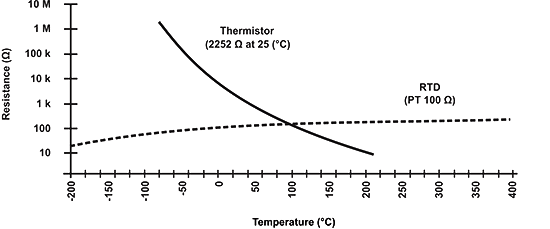
As can be seen from the figure, the NTC thermistors have a much steeper resistance-temperature slope compared to platinum alloy RTDs, which translates to better temperature sensitivity. Even so, RTDs remain the most accurate sensors with their accuracy being ±0.5 % of the measured temperature, and they are useful in the temperature range between -200 and 800 °C, a much wider range than that of NTC temperature sensors.
Comparison to other temperature sensors#
Compared to RTDs, the NTC thermistors have a smaller size, faster response, greater resistance to shock and vibration at a lower cost. They are slightly less precise than RTDs. The precision of NTC thermistors is similar to thermocouples. However thermocouples, can withstand very high temperatures (in the order of 600 °C) and are used in these applications instead of NTC thermistors. Even so, NTC thermistors provide greater sensitivity, stability and accuracy than thermocouples at lower temperatures and are used with less additional circuitry and therefore at a lower total cost. The cost is additionally lowered by the lack of need for signal conditioning circuits (amplifiers, level translators, etc.) that are often needed when dealing with RTDs and always needed for thermocouples.
Self-heating effect#
The self-heating effect is a phenomenon that takes place whenever there is a current flowing through the NTC thermistor. Since the thermistor is basically a resistor, it dissipates power as heat when there is a current flowing through it. This heat is generated in the thermistor core and affects the precision of the measurements. The extent to which this happens depends on the amount of current flowing, the environment (whether it is a liquid or a gas, whether there is any flow over the NTC sensor and so on), the temperature coefficient of the thermistor, the thermistor’s total area and so on. The fact that the resistance of the NTC sensor and therefore the current through it depends on the environment is often used in liquid presence detectors such as those found in storage tanks.
Heat capacity#
The heat capacity represents the amount of heat required to increase the temperature of the thermistor by 1 °C and is usually expressed in mJ/°C. Knowing the precise heat capacity is of great importance when using an NTC thermistor sensor as an inrush-current limiting device, as it defines the response speed of the NTC temp sensor.
Construction and Properties of NTC Thermistors#
Materials typically involved in the fabrication of NTC resistors are platinum, nickel, cobalt, iron and oxides of silicon, used as pure elements or as ceramics and polymers. NTC thermistors can be classified into three groups, depending on the production process used.
Typical Applications#
NTC thermistors are used in a broad spectrum of applications. They are used to measure temperature, control temperature, and compensate for temperature. They can also be used to detect the absence or presence of a liquid, as current limiting devices in power supply circuits, for temperature monitoring in automotive applications, and in many more applications. NTC sensors can be divided into three groups, depending on the electrical characteristic exploited in an application.
Bead thermistors#
These NTC thermistors are made from platinum alloy lead wires directly sintered into the ceramic body. They generally offer fast response times, better stability and allow operation at higher temperatures than Disk and Chip NTC sensors, however they are more fragile. It is common to seal them in glass, to protect them from mechanical damage during assembly and to improve their measurement stability. The typical sizes range from 0.075 – 5 mm in diameter.
Disk and Chip thermistors#
These NTC thermistors have metalized surface contacts. They are larger and, as a result, have slower reaction times than bead type NTC resistors. However, because of their size, they have a higher dissipation constant (power required to raise their temperature by 1 °C). Since the power dissipated by the thermistor is proportional to the square of the current, they can handle higher currents much better than bead type thermistors. Disk type thermistors are made by pressing a blend of oxide powders into a round die and then sintering at high temperatures. Chips are usually fabricated by a tape-casting process where a slurry of material is spread out as a thick film, dried and cut into shape. The typical sizes range from 0.25 to 25 mm in diameter.
Glass encapsulated NTC thermistors#
These are NTC temperature sensors sealed in an airtight glass bubble. They are designed for use with temperatures above 150 °C, or for printed circuit board mounting, where ruggedness is a must. Encapsulating a thermistor in glass improves the stability of the sensor and protects the sensor from the environment. They are made by hermetically sealing bead type NTC resistors into a glass container. The typical sizes range from 0.4 to 10 mm in diameter.
NTC Thermistor Symbol#
The following symbol is used for a negative temperature coefficient thermistor, according to the IEC standard.
 NTC thermistor (IEC standard)
What is an RTD temperature sensor?#
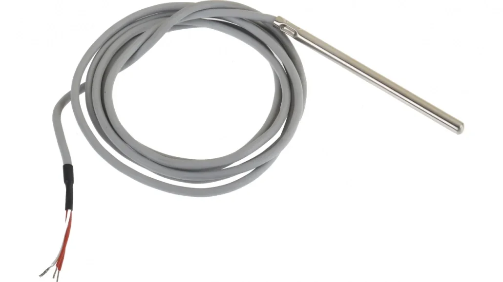
An RTD stands for “Resistance Temperature Detector” and it is a sensor whose resistance changes when its temperature changes and it is used to measure temperature. The RTD’s resistance increases linearly when the temperature increases. Many RTDs are called wire wound. They consist of fine wire wrapped around a glass or ceramic core. The wire is made of platinum. Another interesting thing is that the RTD elements are normally housed in a protective probe to protect them from the environment they are immersed in and to make them more robust. Inexpensive RTDs are called thin film RTDs. They consist of a base ceramic with a fine Platinum track deposited on it.
RTD working principle#
the RTD follows a basic principle. When the temperature of a metal increases, the resistance to the flow of electricity increases as well. An electrical current is passed through the sensor, the resistance element is used to measure the resistance of the current being passed through it. As the temperature of the resistance element increases the electrical resistance also increases. The electrical resistance is measured in Ohms. The resistance value can then be converted into temperature based on the characteristics of the element. Usually, the response time for an RTD is between 0.5 and 5 seconds. This makes them very suitable for many applications.
RTD sensors types#
Resistance Temperature Detectors can be categorised into two types of RTDs. Their type is based on the construction of the temperature-sensing element. The first type contains wire-would elements, while the second type contains thin-film elements.
Thin-film RTDs#
The thin-film RTD elements are made by depositing a thin layer of metal which in most cases is platinum on a ceramic substrate material. The metal film is laser cut or etched into an electrical circuit pattern that provides the specified amount of resistance. Lead wires are then attached, and a thin protective glass coating is applied to the entire element.
The advantages of thin-film RTDs are that they are reliable and are produced at a low cost. Moreover, they are more damage resistant from vibrations than the other types of resistance temperature detectors.
Wire-wound RTDs#
The other type of RTD is wire-would. Its sensing element comprises a small coil of ultra-thin platinum wire. The wire coil is commonly packaged inside a ceramic or glass tube or the wire can be wound around the outside of a ceramic or glass housing material. The advantages of wire-wound RTDs are that they are very accurate and those with glass cores can readily be immersed in many liquids, while those with ceramic cores can be used to accurately measure extremely high temperatures. The disadvantages of wire-would RTDs are that they are more expensive to produce than thin-film and they are more vibration-sensitive.
What are PTC Thermistors?#
PTC stands for “Positive Temperature Coefficient”. PTC thermistors are resistors with a positive temperature coefficient, which means that the resistance increases with increasing temperature.
PTC thermistors are divided into two groups based on the materials used, their structure, and the manufacturing process. The first group of PTC thermistors is comprised of silistors, which use silicon as the semiconducting material. They are used as PTC temperature sensors for their linear characteristic.
The second group is the switching type PTC thermistor. The switching type PTC thermistor has a highly nonlinear resistance-temperature curve. When the switching type PTC thermistor is heated, the resistance starts to decrease at first, until a certain critical temperature is reached. As the temperature is further increased above that critical value, the resistance increases dramatically. This type of PTC thermistors is widely used in PTC heaters, sensors etc. Polymer PTC thermistors, made of a special plastic, are part of this second group and are often used as resettable fuses.
PTC Thermistor Definition#
A PTC thermistor is a thermally sensitive resistor for which the resistance increases significantly with increasing temperature.
Characteristics of PTC Thermistors#
Silistors have a linear resistance-temperature characteristic, with a slope that is relatively small through most of their operational range. They may exhibit a negative temperature coefficient at temperatures above 150 °C. Silistors have temperature coefficients of resistance of about 0.7 to 0.8% / °C.
Switching PTC thermistors are usually made of polycrystalline ceramic materials that are highly resistive in their original state and are made semi-conductive by the addition of dopants. They are mostly used as PTC self-regulating heaters. The transition temperature of most switched PTC thermistors is between 60 and 120 °C. However, there are special application devices manufactured that can switch as low as 0 °C or as high as 200 °C.
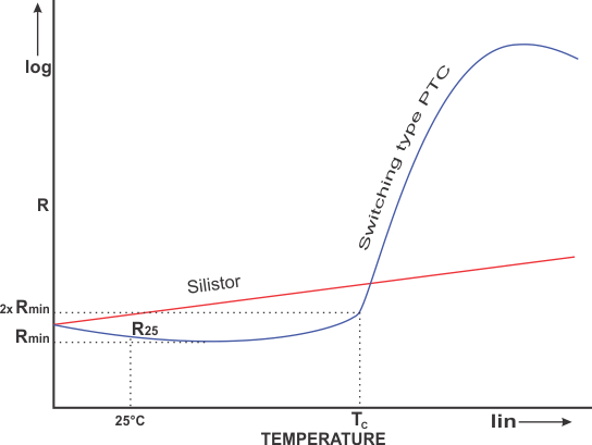 The resistance-temperature (R-T) characteristics of a PTC thermistor and a silistor
Transition temperature (Tc)#
As can be seen from the figure, switching PTC thermistors have a slightly negative temperature coefficient up to the point of minimum resistance. Above this point, it experiences a slightly positive coefficient up to the moment it reaches its transition temperature (TC). This temperature is also sometimes referred to as the switch or Curie temperature. The switch temperature is the temperature at which the resistance of switching type PTC thermistors starts to rise rapidly. The Curie temperature is most of the time defined as the temperature at which the resistance is twice the value of the minimum resistance.
Minimum resistance (Rmin)#
The minimum resistance of a PTC thermistor is the lowest resistance that can be measured on a switched type PTC thermistor, as seen on the R-T curve. It is the point on the curve after which the temperature coefficient turns positive.
Rated resistance (\(R_{25}\))#
The rated PTC resistance is normally defined as the resistance at 25 °C. It serves to classify the thermistors according to their resistance value. It is measured with a low current that does not heat the thermistor enough to affect the measurement.
Modes of Operation#
Depending on the application, PTC thermistors can be used in two modes of operation; self-heated and sensing (also called zero-power).
Self-heated mode#
Self-heated applications exploit the fact that when a voltage is applied to a thermistor and sufficient current flows through it, its temperature increases. As the Curie temperature is approached, the resistance increases dramatically, allowing much less current to flow. This behavior can be seen from the figure on the left. The resistance change near the Curie temperature can be several orders of magnitude within a temperature span of only a few degrees. If the voltage remains constant, the current will stabilize at a certain value as the thermistor reaches thermal equilibrium. The equilibrium temperature depends on the voltage applied, as well as the thermal dissipation factor of the thermistor. This mode of operation is often utilized when designing temperature dependent time delay circuits.
Sensing (zero-power) mode#
In this mode of operation, the power consumption of the thermistor is so small that it has a negligible effect on the thermistor’s temperature and therefore resistance, in contrast to the self-heated mode. The sensing mode is usually used when measuring temperature using the R-T curve as a reference.
Typical Applications for PTC Thermistors#
Self-regulating heaters#
If there is a current running through a switching PTC thermistor, it will auto-stabilize at a certain temperature. It means that if the temperature is decreased, the resistance will decrease as well, allowing more current to flow and thus heating the device. Similarly, if the temperature is increased, the resistance is increased as well, limiting the current passing through the device, thus cooling it down. The PTC thermistor has then reached a point where the power consumed is practically independent of the voltage over a relatively wide voltage range. These PTC thermistors are often made of ceramics in various shapes and sizes and because of their design flexibility, PTC ceramic heaters are a great choice for providing controlled electrical heat. For increased heat transfer, the ceramic heating elements can be mounted on aluminum heat sinks or grids. There are also printed PTC heater inks that can be screen-printed onto polymer substrates to create PTC heaters.
Over-current protection#
Switched PTC thermistors are used as over-current limiters or resettable fuses in various circuits. In the case of an over-current situation, the thermistor body temperature rises and quickly reaches the transition temperature. This results in the resistance of the PTC thermistor sharply rising, limiting current in the circuit. When the over-current or short-circuit situation is solved and the thermistor is cooled down again, the circuit will function as normal again. In this way it acts as a automatic resettable fuse. Normally polymer PTC thermistors are used for this application. They are known under different trade names such as polyfuse, polyswitch, and multifuse.
Time delay#
A time delay in a circuit can be provided using the time needed for a PTC thermistor to heat up enough to switch from its low resistance state to a high resistance state, and vice versa. The time delay is dependent upon the size, ambient temperature and the voltage it is connected to, as well as the circuit it is utilized in. An example of time delay use for PTC thermistors is their use in fluorescent lamps. When power is first applied, the thermistor is in a cold state (room temperature). The lamp voltage is below the ignition voltage and the current flowing through the circuit heats up the electrodes and the PTC at the same time. When the Curie temperature is reached, the PTC will switch, the voltage across the lamp will exceed the ignition voltage and the lamp will begin normal operation. Preheating of the electrodes extends lamp life significantly, which is why PTC thermistors are used in such circuits.
Motor starting#
Some electrical motors have a separate startup winding which needs to be powered only during motor startup. In such cases, the self-heating effect of a PTC thermistor can be used in a series connection with such a winding. When the circuit is turned on, the PTC thermistor has a low resistance, allowing current to pass through the startup winding. As the motor starts, the PTC thermistor heats up and at one point switches to a high resistance state. The time needed for this to occur is calculated based on the required motor startup time. Once heated up, the current through the PTC thermistor becomes negligible, and this shuts off the startup winding current.
Liquid level sensing#
These applications rely on the change in the dissipation constant when the conduction and convection heat transfer are increased. An increase in the dissipation constant, resulting from the contact between the device and a liquid or an increased air flow over the device will lower the thermistor’s operating temperature and increase the amount of power needed to maintain a given body temperature. The power increase can be measured and indicates to the system that the thermistor is, for example, immersed in a liquid.
PTC Thermistor Symbol#
The following symbol is used for a positive temperature coefficient thermistor, according to the IEC standard.
 PTC thermistor symbol (IEC standard)
References:#
https://eepower.com/resistor-guide/resistor-types/ntc-thermistor/
https://eepower.com/resistor-guide/resistor-types/ptc-thermistor/
https://peaksensors.com/blog/resistance-thermometer/what-is-rtd-sensor-and-how-does-it-work/